

The Ultimate Guide to CNC Machining 304 and 316 Stainless Steel
Custom CNC machining for 304 & 316 stainless steel. Strict inspection, MTC provided, corrosion-resistant precision parts for medical, marine & machinery.
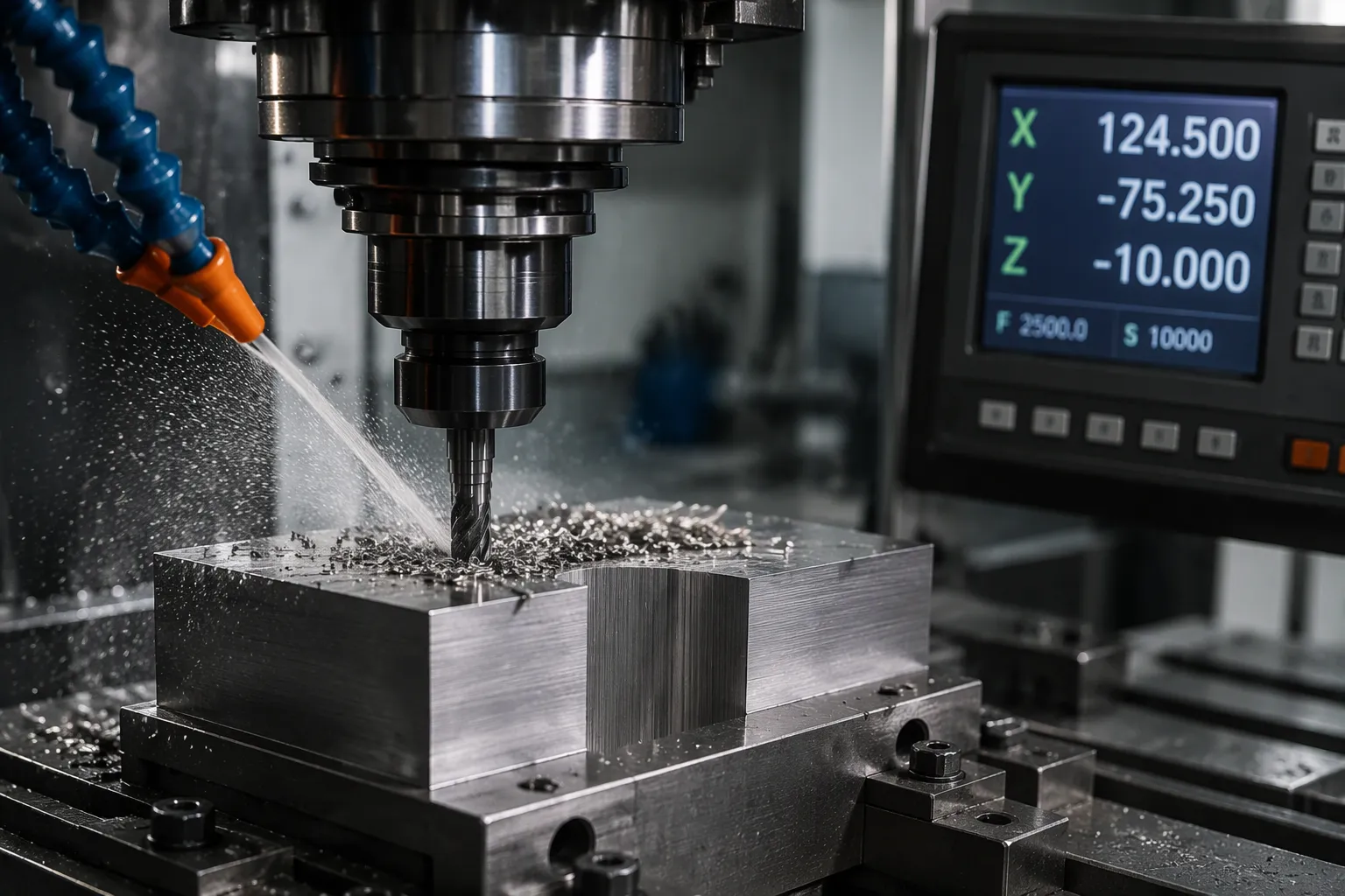
The 304 versus 316 decision shapes machinability, tool life, corrosion performance, and total part cost. Engineers who write a professional B2B knowledge article about stainless steel machining and custom stainless steel parts manufacturing for American and European mechanical engineers must treat this choice as a cost driver. Grade 304 serves general-purpose work at a lower price. Grade 316 adds molybdenum for superior corrosion resistance, yet it costs more and machines slightly harder. Both grades are austenitic and work harden identically, so the machining principles stay the same and only the parameters change.
Key Takeaways
- Choose 304 for general use and lower cost. Choose 316 for harsh environments with chlorides.
- Adjust cutting speeds and feeds for each grade. Use slower speeds for 316 to protect tool life.
- Passivate both grades after machining. This step removes free iron and prevents rust.
304 vs. 316: Material Properties
Chemical Composition at a Glance
Both grades share an austenitic structure built on iron, chromium, and nickel. Chromium forms the passive oxide layer that protects the surface. Nickel stabilizes the austenite phase and supports formability. The key difference sits in molybdenum. Grade 316 adds 2–3% molybdenum, and this single element drives most of the performance gap between the two grades.
| Element | 304 (%) | 316 (%) |
|---|---|---|
| Chromium | 18–20 | 16–18 |
| Nickel | 8–10.5 | 10–14 |
| Molybdenum | — | 2–3 |
| Carbon | ≤0.08 | ≤0.08 |
Corrosion Resistance Compared
Grade 304 handles most indoor and general-purpose environments well. It resists oxidizing acids, fresh water, and many food-contact conditions. Grade 316 extends that protection into chloride-rich settings. The molybdenum content resists pitting and crevice corrosion from salt water, de-icing salts, and chloride process streams. Engineers specify 316 for marine hardware, medical instruments, and chemical equipment for this reason.
Strength and Temperature Behavior
The two grades show similar tensile strength in the annealed condition, typically around 75–90 ksi. Grade 316 holds slightly better strength at elevated temperatures. Both grades retain good toughness at cryogenic temperatures. Neither grade responds to heat treatment for hardening. Cold working raises strength in both grades, and this behavior connects directly to the work-hardening challenges covered in the next section.
Machinability of 304 and 316
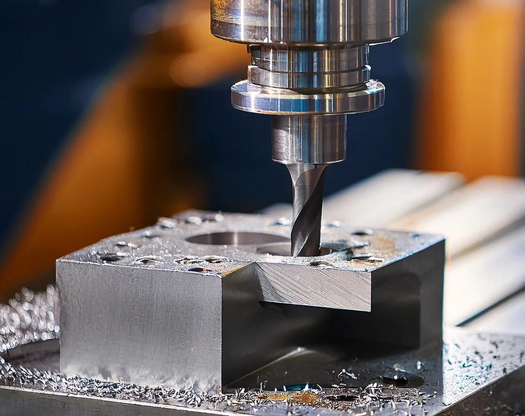
Austenitic stainless steels carry a reputation for difficult machining, and both 304 and 316 earn it honestly. The two grades share the same face-centered cubic crystal structure, the same rapid work-hardening response, and the same low thermal conductivity. A machinist who masters one grade can transfer most of that knowledge to the other. The differences lie in degree, not in kind. Grade 316 machines at roughly 10–15% lower cutting speeds than 304 under comparable conditions, and the molybdenum addition makes the chip slightly tougher. Understanding the three mechanisms below gives a shop the foundation to set parameters with confidence.
Why Work Hardening Matters
Work hardening describes a simple phenomenon with expensive consequences. Austenitic stainless steel deforms plastically under cutting pressure, and the deformed layer becomes harder and stronger than the metal beneath it. Grade 304 can climb from roughly 90 HRB in the annealed state to 30 HRC or higher in a worked surface layer. Grade 316 behaves the same way. The rate of hardening is steep and fast, and it punishes any tool that rubs instead of cuts.
The practical danger appears at the depth of cut. A light pass that stays within the previously hardened layer forces the insert to cut hard metal instead of soft metal. Each subsequent pass then hardens the next layer, and the workpiece grows progressively more difficult to machine. The effect compounds on repeated finishing passes, on dwell at the start of a cut, and on any tool that loses sharpness mid-operation. A dull edge rubs the surface, generates heat, and hardens the very material it must remove.
Three habits keep work hardening under control. First, maintain a minimum depth of cut that reaches below the hardened zone, typically at least 0.5–1.0 mm (0.020–0.040 in) for turning and comparable radial engagement for milling. Second, keep the tool engaged and avoid interrupted cuts wherever the part geometry allows. Third, replace or index inserts at the first sign of flank wear rather than pushing through a worn edge. A sharp, positive-rake tool that shears cleanly generates far less hardening than a worn tool that plows.
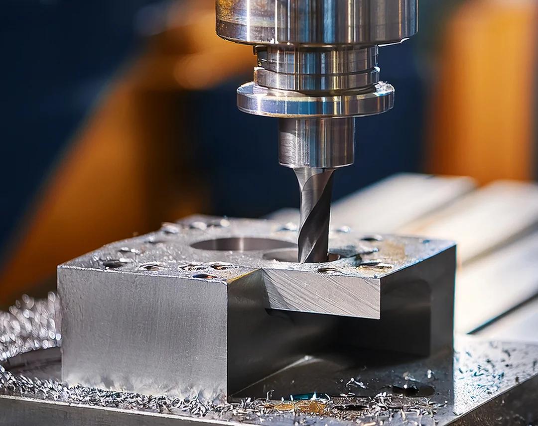
Climb milling offers another lever on CNC equipment. The cutter engages the workpiece at maximum chip thickness and exits at zero thickness, which keeps the cutting action inside the fresh material and away from the hardened skin. Conventional milling does the opposite and tends to rub at entry. For finishing operations on 304 and 316, climb milling with a sharp cutter produces a cleaner surface and less subsurface damage.
Thermal Conductivity and Heat Control
Stainless steel conducts heat poorly, and this single property reshapes the entire thermal picture of a cut. Grade 304 carries a thermal conductivity of about 16 W/m·K at room temperature. Grade 316 sits slightly lower at roughly 14 W/m·K. Carbon steel, by comparison, conducts heat at roughly three times that rate. The comparison matters because the chip cannot carry heat away quickly in stainless steel.
| Property | 304 | 316 |
|---|---|---|
| Thermal conductivity (W/m·K, room temp) | ~16 | ~14 |
| Relative machinability rating (free-machining steel = 100%) | ~45% | ~35–40% |
The heat has nowhere to go except into the tool and the workpiece. Cutting-zone temperatures at the tool edge can exceed 1,000°C (1,800°F) in continuous turning, and most of that energy concentrates within a narrow band near the cutting edge. Tool wear accelerates sharply above certain temperature thresholds. The workpiece also expands as it heats, and uneven heating across a part distorts dimensions between roughing and finishing.
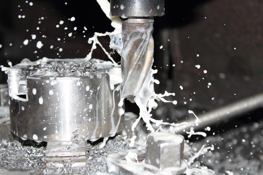
Effective heat control combines several tactics. Flood coolant directed precisely at the cutting zone removes heat and lubricates the chip-tool interface. High-pressure coolant through the tool delivers fluid exactly where the heat concentrates and breaks the chip more reliably. Generous coolant volume matters more than pressure alone for roughing operations. For finishing passes, a steady, well-aimed stream prevents thermal shock to carbide inserts and protects surface integrity.
Cutting speed acts as the primary thermal control valve. Every 20% reduction in surface speed lowers edge temperature noticeably and extends tool life. Shops that run 304 and 316 at the same speeds they use for carbon steel burn through inserts quickly. Conservative speeds, combined with adequate feed to keep the tool cutting rather than rubbing, form the thermal strategy that works for both grades.
Chip Formation and Surface Finish
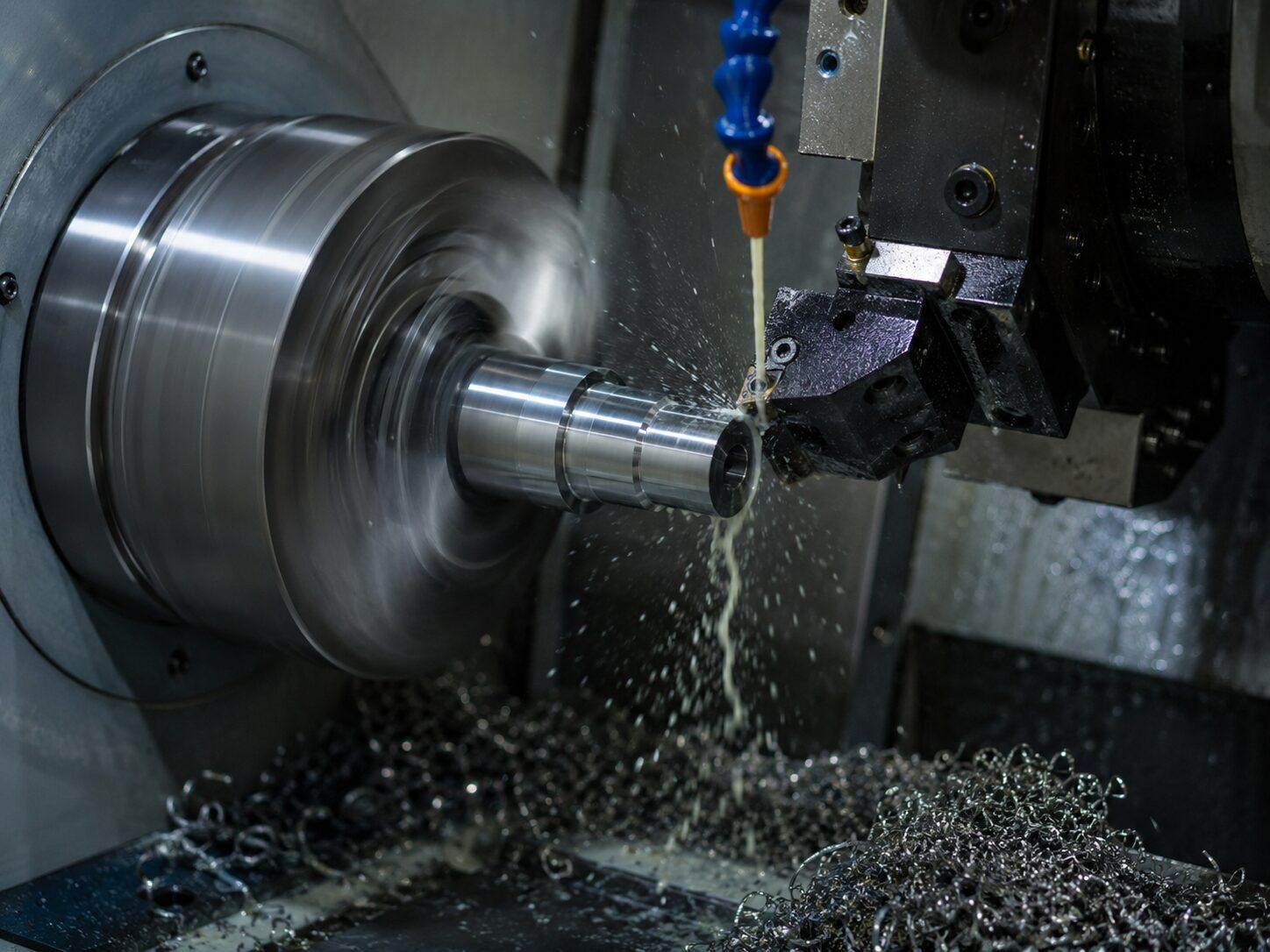
Austenitic stainless steels produce continuous, stringy chips that resist breaking. The chip curls tightly and work-hardens as it forms, and it can wrap around the tool, the workpiece, or the chuck. Chip control becomes a safety issue as well as a quality issue. Long chips tangle, scratch finished surfaces, and interrupt the cutting process when they break free.
Chip breakers designed for stainless steel feature a wider groove and a more open geometry than breakers for carbon steel. The chip must curl tightly enough to break against the workpiece or the tool face without excessive bending force. Feed rate drives chip thickness, and chip thickness drives breakability. A feed that is too light produces a thin, tough chip that will not break. A heavier feed produces a thicker chip that fractures more readily. The counterintuitive rule holds: increasing feed often improves chip control in stainless steel, while reducing feed makes the problem worse.
Built-up edge represents the other major chip-related problem. At certain speed ranges, work-hardened stainless steel particles weld to the cutting edge and form a lump of material that grows and breaks away in cycles. Each cycle leaves a fragment embedded in the machined surface and a small crater on the tool. Built-up edge roughens the finish, changes the effective tool geometry, and accelerates wear. Higher surface speeds, sharp positive-rake geometries, and effective lubrication all suppress built-up edge formation.
Surface finish in 304 and 316 depends heavily on the last pass. A finishing insert with a small nose radius and a sharp edge, run at moderate speed and light but sufficient depth, produces a surface in the 0.8–1.6 µm Ra range on a stable setup. Worn tools, built-up edge, and vibration all degrade the finish quickly. Rigid workholding and minimal tool overhang pay dividends here, because stainless steel transmits cutting forces into the setup with little damping. A rigid setup lets the finishing pass run at the parameters the insert was designed for, and the surface quality follows.
Tooling Selection for Stainless Steel

Tooling choice separates a productive stainless steel job from a costly one. Both 304 and 316 demand sharp edges, rigid setups, and heat-resistant cutting materials. The right combination protects tool life and holds surface finish within specification.
Carbide Grades and Geometries
Austenitic stainless steels call for tough, fine-grain carbide substrates. A grade in the ISO P25–P35 range balances wear resistance against edge strength. Harder substrates resist flank wear at higher speeds. Tougher substrates survive interrupted cuts and heavy feeds without chipping.
Geometry matters as much as grade. A positive rake angle shears the material cleanly and lowers cutting forces. Sharp edges reduce work hardening at the cut zone. A small hone protects the edge without dulling it. Inserts with open chipbreaker grooves curl the stringy chip and break it reliably.
Coatings That Extend Tool Life
Coatings act as a thermal barrier between the hot chip and the carbide substrate. They slow diffusion wear and resist built-up edge. The table below compares common options.
| Coating | Best Use | Key Benefit |
|---|---|---|
| PVD TiAlN | General turning and milling | High hardness, sharp edges |
| PVD AlTiN | Heavy roughing | Heat resistance at high speed |
| CVD multilayer | Continuous turning | Thick wear resistance layer |
PVD coatings suit sharp-edged finishing tools. CVD coatings favor heavy roughing where edge strength dominates.
Coolant and Lubrication Strategy
Flood coolant removes heat and flushes chips from the cutting zone. High-pressure coolant through the tool targets the edge directly and improves chip breaking. A concentration of 8–12% for water-soluble coolant supports both cooling and lubrication. Shops should aim the stream at the cutting edge, not the chip. Consistent flow prevents thermal shock to carbide inserts.
Cutting Speeds and Feeds for 304 and 316
Cutting data for austenitic stainless steel follows a narrow window. Run too fast and the insert edge overheats and fails within minutes. Run too slow and the tool rubs, work hardens the surface, and ruins the next pass. The numbers below give shops a reliable starting point for 304 and 316. Every shop should treat these values as a baseline and adjust them for machine rigidity, toolholder stiffness, coolant delivery, and part geometry.
Surface speed (SFM) drives tool life more than any other variable in stainless steel. Feed rate controls chip thickness and chip breaking. Depth of cut determines whether the tool reaches below the work-hardened layer. All three values work together, and changing one without the others usually causes trouble.
Recommended Parameters for 304
Grade 304 machines at moderate speeds with coated carbide tooling. The following values apply to coated carbide inserts under flood coolant on a rigid setup.
For turning operations, a surface speed of 150–200 SFM (45–60 m/min) suits roughing with P25–P35 grade inserts. Finishing passes run faster at 200–250 SFM (60–75 m/min) with a sharp positive-rake insert. Feed rates range from 0.008–0.012 IPR (0.2–0.3 mm/rev) for roughing and 0.004–0.008 IPR (0.1–0.2 mm/rev) for finishing. Roughing depth of cut should reach at least 0.080 in (2 mm) to stay below the hardened zone. Finishing depth of cut should not fall below 0.020 in (0.5 mm) for the same reason.
Milling 304 calls for a surface speed of 250–350 SFM (75–105 m/min) with coated carbide end mills. Feed per tooth runs 0.002–0.004 in (0.05–0.10 mm) for roughing and 0.001–0.002 in (0.025–0.05 mm) for finishing. Radial engagement should stay at 50–70% of cutter diameter for roughing. Climb milling protects the edge and improves surface finish. A rigid setup with minimal tool overhang keeps vibration under control.
Drilling 304 with high-speed steel or cobalt drills runs at 30–50 SFM (10–15 m/min) with a feed of 0.004–0.008 IPR (0.1–0.2 mm/rev), scaled to drill diameter. Solid carbide drills push surface speed to 150–200 SFM (45–60 m/min) with through-coolant delivery. Peck drilling helps clear chips and prevents the drill from rubbing on retraction.
A common mistake on 304 is running too light a finishing pass. A depth below 0.020 in (0.5 mm) keeps the tool inside the hardened skin and shortens insert life dramatically.
Recommended Parameters for 316
Grade 316 machines at roughly 10–15% lower surface speeds than 304. The molybdenum addition raises hot strength and makes the chip tougher. The same tooling and coolant strategy applies, with adjusted values.
Turning 316 runs at 130–180 SFM (40–55 m/min) for roughing and 180–220 SFM (55–65 m/min) for finishing. Feed rates stay close to the 304 values: 0.008–0.012 IPR (0.2–0.3 mm/rev) for roughing and 0.004–0.007 IPR (0.1–0.18 mm/rev) for finishing. Depth of cut rules stay identical. The tool must reach below the hardened layer on every pass.
Milling 316 uses a surface speed of 220–300 SFM (65–90 m/min) with coated carbide. Feed per tooth runs 0.002–0.003 in (0.05–0.08 mm) for roughing and 0.001–0.002 in (0.025–0.05 mm) for finishing. The tougher chip demands a more open chipbreaker and slightly higher feed per tooth to break reliably. Inserts should carry a PVD TiAlN or AlTiN coating for heat resistance.
Drilling 316 with high-speed steel or cobalt drills runs at 25–40 SFM (8–12 m/min). Solid carbide drills run at 130–180 SFM (40–55 m/min) with through-coolant. Feed per revolution stays in the 0.004–0.007 IPR (0.1–0.18 mm/rev) range. Grade 316 work hardens quickly under a dull drill, so operators should replace or sharpen drills at the first sign of wear.
Side-by-Side Comparison Table
The table below consolidates the recommended starting parameters for both grades. Values assume coated carbide tooling, flood coolant, and a rigid setup. Shops should verify and fine-tune these numbers against their own machine and tooling conditions.
| Operation | Parameter | 304 | 316 |
|---|---|---|---|
| Turning (roughing) | Surface speed | 150–200 SFM (45–60 m/min) | 130–180 SFM (40–55 m/min) |
| Turning (roughing) | Feed rate | 0.008–0.012 IPR (0.2–0.3 mm/rev) | 0.008–0.012 IPR (0.2–0.3 mm/rev) |
| Turning (roughing) | Depth of cut (min.) | 0.080 in (2 mm) | 0.080 in (2 mm) |
| Turning (finishing) | Surface speed | 200–250 SFM (60–75 m/min) | 180–220 SFM (55–65 m/min) |
| Turning (finishing) | Feed rate | 0.004–0.008 IPR (0.1–0.2 mm/rev) | 0.004–0.007 IPR (0.1–0.18 mm/rev) |
| Turning (finishing) | Depth of cut (min.) | 0.020 in (0.5 mm) | 0.020 in (0.5 mm) |
| Milling (roughing) | Surface speed | 250–350 SFM (75–105 m/min) | 220–300 SFM (65–90 m/min) |
| Milling (roughing) | Feed per tooth | 0.002–0.004 in (0.05–0.10 mm) | 0.002–0.003 in (0.05–0.08 mm) |
| Milling (finishing) | Surface speed | 250–350 SFM (75–105 m/min) | 220–300 SFM (65–90 m/min) |
| Milling (finishing) | Feed per tooth | 0.001–0.002 in (0.025–0.05 mm) | 0.001–0.002 in (0.025–0.05 mm) |
| Drilling (HSS/cobalt) | Surface speed | 30–50 SFM (10–15 m/min) | 25–40 SFM (8–12 m/min) |
| Drilling (HSS/cobalt) | Feed rate | 0.004–0.008 IPR (0.1–0.2 mm/rev) | 0.004–0.007 IPR (0.1–0.18 mm/rev) |
| Drilling (solid carbide) | Surface speed | 150–200 SFM (45–60 m/min) | 130–180 SFM (40–55 m/min) |
| Drilling (solid carbide) | Feed rate | 0.004–0.008 IPR (0.1–0.2 mm/rev) | 0.004–0.007 IPR (0.1–0.18 mm/rev) |
Three patterns stand out in the table. Grade 316 runs consistently slower on surface speed across every operation. Feed rates stay nearly identical between the grades, because chip thickness rules do not change with the alloy addition. Depth of cut minimums stay the same for both grades, because work hardening behaves the same way in each.
Shops that machine both grades benefit from a simple rule. Start with the 304 parameters, then reduce surface speed by 10–15% for 316. Keep the feed and depth of cut unchanged. This rule protects tool life on 316 without sacrificing chip control or surface finish.
Operators should watch three signals during the first parts of any run. Rising spindle load points to work hardening or a dull edge. Color change on the chip signals excess heat and calls for a speed reduction. Chatter or vibration points to setup rigidity problems, not parameter problems. A shop that reads these signals and adjusts within the first few parts protects tool life and part quality for the rest of the order.
Design Tips for Cost-Effective Machining
Features That Drive Up Cost
Deep pockets, sharp internal corners, and thin walls raise machining cost on both grades. Deep pockets demand long-reach tools with reduced rigidity. Sharp internal corners force small cutters and slow passes. Thin walls deflect under cutting pressure and require light passes with extra finishing steps. Designers who open corner radii and limit pocket depth to four times the cutter diameter cut cycle time noticeably.
Tolerances and Surface Finish Calls
Every tolerance tighter than the process capability adds inspection time and scrap risk. Standard machining holds ±0.005 in (±0.13 mm) on most features without special effort. Surface finish calls below 63 µin Ra (1.6 µm Ra) require additional finishing passes. The table below shows typical cost impact.
| Callout | Cost Impact | Recommendation |
|---|---|---|
| ±0.005 in (±0.13 mm) | Baseline | Specify only where function demands |
| ±0.001 in (±0.025 mm) | High | Reserve for mating surfaces |
| 63 µin Ra (1.6 µm Ra) | Baseline | Standard for most parts |
| 32 µin Ra (0.8 µm Ra) | Moderate | Specify on sealing faces only |
Designing Around Work Hardening
Work hardening punishes designs that force repeated light passes. A feature that requires many shallow cuts hardens the surface layer and shortens tool life. Designers should allow roughing passes deep enough to reach below the hardened zone. Generous corner radii and open geometry let the tool stay engaged and cut continuously. Interrupted cuts and thin sections that vibrate force light passes and compound the problem. A design that gives the cutter room to work protects tool life and holds cost down.
Post-Machining Treatments
Passivation Explained
Machining leaves free iron particles embedded in the stainless surface. These particles rust and create the appearance of a defective part. Passivation removes them. The process immerses the part in a nitric or citric acid bath. The acid dissolves free iron while the chromium-rich passive layer rebuilds itself. ASTM A967 and ASTM A380 define the accepted procedures. A properly passivated 304 part shows no rust after a standard salt spray test.
When 316 Still Needs Passivation
Molybdenum raises corrosion resistance, yet it does not eliminate surface contamination. Cutting tools, fixtures, and handling transfer iron to the surface of 316 parts. Weld heat tint also depletes chromium near the weld zone. Passivation restores the passive layer in both cases. Medical instruments, marine fittings, and pharmaceutical equipment routinely require passivation on 316, even though the base metal resists chlorides well.
Other Finishing Options
Several finishes complement passivation or replace it for specific service conditions. The table below summarizes the common choices.
| Finish | Purpose | Typical Application |
|---|---|---|
| Passivation | Removes free iron, restores oxide layer | General corrosion protection |
| Sand blasting | Uniform matte appearance, light deburring | Cosmetic parts, brackets |
| Electropolishing | Bright surface, enhanced corrosion resistance | Medical, semiconductor |
| Pickling | Removes weld scale and heat tint | Post-weld assemblies |
Sand blasting suits parts that need a consistent matte look. Electropolishing goes further than passivation and delivers a mirror-bright surface with superior corrosion performance. Pickling removes the heavy oxide scale that welding leaves behind. Engineers should specify the finish that matches the service environment, not simply the lowest-cost option.
Quality Evaluation and Applications
Inspecting Machined Stainless Parts
Inspection confirms that a machined stainless part meets its drawing before it ships. Dimensional checks with calipers, micrometers, and CMM equipment verify critical features against tolerance. Surface finish testing with a profilometer confirms the Ra callout on sealing faces and bearing surfaces. Corrosion testing, such as salt spray or copper sulfate testing, reveals free iron contamination after passivation. Material certificates tie each lot back to its mill heat number and support full traceability. A supplier that documents every inspection step gives engineers confidence in the delivered part.
Best-Fit Applications for 304
Grade 304 suits general-purpose service where chlorides stay low. Typical uses include food processing equipment, kitchen fixtures, architectural trim, storage tanks, and general mechanical brackets. Medical equipment housings and support frames also fit well when the environment stays clean and controlled. The grade offers strong corrosion resistance at a lower material cost, and it machines faster than 316. Engineers who face moderate corrosion demands and tight budgets often find 304 the practical choice.
Best-Fit Applications for 316
Grade 316 earns its place in chloride-rich and aggressive environments. Marine accessories, boat fittings, and dock hardware resist salt water pitting with the molybdenum addition. Chemical processing equipment, pharmaceutical vessels, and medical implants rely on 316 for resistance to harsh process streams and cleaning agents. Coastal architectural components and de-icing salt exposure also favor 316. The grade costs more and machines slower, yet it protects parts where 304 would pit or stain early.
Cost Comparison: 304 vs. 316 Machined Parts
Material Cost per Pound
Grade 316 carries a higher mill price than 304. The molybdenum addition and higher nickel content drive the gap. Buyers typically see 316 cost 30–50% more per pound than 304, and the spread widens when nickel and molybdenum markets run high. The table below shows typical relative pricing.
| Cost Factor | 304 | 316 |
|---|---|---|
| Relative material price per pound | Baseline | +30–50% |
| Relative machinability | Baseline | ~10–15% slower |
Machining Cost and Tool Wear
Machining cost often outweighs material cost on complex parts. Grade 316 runs at lower surface speeds, so cycle times stretch 10–15% longer. The tougher chip raises tool wear slightly, and insert consumption climbs. A shop that machines 316 with 304 parameters burns through tooling fast. Correct parameters keep the wear gap modest. Rigid setups, sharp edges, and generous coolant protect tool life in both grades.
When the 316 Premium Pays Off
Grade 316 justifies its premium in chloride-rich service. Marine hardware, chemical equipment, and coastal installations avoid pitting and staining that would shorten part life. A part that fails early costs far more than the material premium. Grade 304 wins on general-purpose work with moderate corrosion demands. Engineers should weigh service environment, part life, and total cost together. The cheaper grade saves money only when it survives the application.
Custom Stainless Steel Parts: A B2B Sourcing Guide for American and European Mechanical Engineers
What to Include in Your RFQ
A complete RFQ shortens the quote cycle and prevents costly revisions later. Engineers should attach 2D drawings and 3D models with clear revision numbers. The package should state the grade (304 or 316), quantity, tolerance callouts, and surface finish requirements. Passivation and inspection standards belong in the same document. A professional B2B knowledge article about stainless steel machining and custom stainless steel parts manufacturing for American and European mechanical engineers should stress one point: ambiguity in the RFQ becomes scrap on the shop floor.
Material Certificates and Traceability
Mill certificates tie each lot to its heat number and chemical composition. Engineers should request certificates to EN 10204 3.1 for European projects or ASTM A484 for American ones. Traceability links the finished part back to the mill heat. This record supports audits in medical, marine, and chemical applications.
Evaluating a Machining Supplier
Supplier evaluation goes beyond price per piece. The table below lists the criteria that matter most.
| Criterion | What to Verify |
|---|---|
| Stainless experience | Track record with 304 and 316 work hardening |
| Inspection capability | CMM, profilometer, documented reports |
| Certificates | Mill certs and passivation records on file |
| Communication | Clear response on drawing questions |
A supplier with stainless steel machining experience controls deformation and protects corrosion resistance. Sample parts and reference customers confirm capability before a full order. Engineers who apply these checks secure reliable custom stainless steel parts manufacturing for American and European mechanical engineers on every project.
Grade 304 delivers cost-effective performance in general environments. Grade 316 earns its premium in chloride-rich or corrosive service.
Matching tooling and parameters to the grade protects tool life and part quality. The grade alone does not determine success.
Engineers should weigh corrosion requirements, budget, and machinability together when they specify a grade. This approach supports a professional B2B knowledge article about stainless steel machining and custom stainless steel parts manufacturing for American and European mechanical engineers.
FAQ
Which grade should an engineer choose for a coastal or marine part?
Grade 316 resists chloride pitting and crevice corrosion far better than 304. Engineers specify 316 for salt water, de-icing salts, and coastal service. Grade 304 suits inland, low-chloride environments at a lower cost.
Why does a light finishing pass damage stainless steel?
A shallow cut stays inside the work-hardened layer. The tool then cuts hard metal instead of soft metal. Operators keep the finishing depth above 0.020 in (0.5 mm) to reach fresh material.
Does grade 316 still need passivation after machining?
Yes. Cutting tools and fixtures deposit free iron on the surface of both grades. Passivation dissolves that contamination and rebuilds the chromium oxide layer. Medical and marine parts routinely require it.
See Also
Avoid Making The Wrong Aluminum Casting Process Choice Ever Again
Related products
-
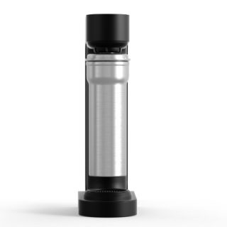
NEW GLASS SODA MAKER BEST CARBONATOR(GLASS BOTTLE) NEW ARRIVALS SODA STREAM MAKER HOUSEHOLD SPARKLING WATER MAKER WITH GLASS BOTTLE
Contact UsNEW GLASS SODA MAKER BEST CARBONATOR(GLASS BOTTLE) NEW ARRIVALS SODA STREAM MAKER HOUSEHOLD SPARKLING WATER MAKER WITH GLASS BOTTLE
-

Rotary kiln incinerator
Contact UsRotary kiln incineration systems are widely adopted in the international industrial waste treatment sector, holding an approximate market share of 85% in this field. They are also recommended by China’s Ministry of Science and Technology and the National Environmental Protection Agency as the preferred furnace type in the National Industrial Waste Treatment Technology Policy. These systems can simultaneously handle sludge, industrial waste and waste with high moisture content. Solid waste is conveyed into the rotary kiln where it undergoes moisture evaporation, volatilization, ignition, and complete combustion. Ash residue is discharged through an outlet at the kiln’s tail end, while the generated flue gas proceeds to a secondary combustion chamber. Here, it mixes with secondary combustion air to ensure thorough burning, leading to the safe and compliant discharge of exhaust gases. Key features of rotary kiln incinerators include their broad adaptability to various wastes, ease of operation and maintenance, and extended service life.
-
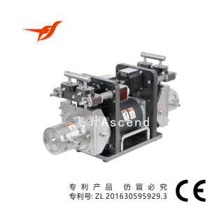
Digital-control Fluid Injection / Filling system
Contact UsFSH-SK10 product series is one of the high efficiency, high precision and high reliability intelligent digital-control dispensing system in high flow. FSH-SK10 is the top choice for automated fluid filling systems and intelligent factory production lines with high-capacity injection pump.
-

RO water Treatment
Contact UsThe reverse osmosis equipment passes the raw water through fine filters, granular activated carbon filters, compressed activated carbon filters, etc., and then pressurizes it through a pump, using a p
Reviews
There are no reviews yet.